This module serves to control four motors. They may be switched on and off and reversed. The power supply of the control circuit and the power supply of the motor are galvanical separated.
The module is controlled by an I2C interface using the IC PCF8574. The signals are amplified using the driver IC ULN2803 and then the relais are switched. Every motor is controlled by two consecutive bits. The lower bit switches the motor on and off and the higher order bit switches to reverse. Here you may see the circuit diagram for one motor.
A problem concerning this circuit is that on powerm up the outputs of the PCF8574 is switched into high state. This is inverted by the ULN2803 (not shown in some data sheets), so they they are switched to low. The relais bobbin is switched against +5V, so on power on all relais pull and all motors start in reverse direction. To avoid this all bits of the PCF8574 have to be set to low during initialization.
Another problem is the high power consumption of the relais. Each Relais consumes 50 mA when it is switched on. If all motors are in reverse operation, so the relais alone will consume 400 mA.
A new module is planned, which will replace the relais by two ICs L293E. This will be a bit more complicated, because it will use a AT90S2313 to control and check the speed of the motors.
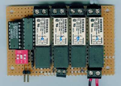
Here you can see a scan of the relais motor module:
© Mario Boller-Olfert 2002 - E-Mail: Kontaktformular - 123-Byte - Marios Welt