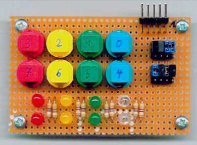
The test module contains 8 push buttons and 8 LEDs. They are available by a 10 pin male connector, whos assignment is similar to that of the digital port connectors on the Atmel STK500 board.
Each bit can be defined by a jumper, to designate it as a push button (input) or an LED (output). Here you can get the simple circuit diagram for one bit.
And here is a scan of the board:
© Mario Boller-Olfert 2002 - E-Mail: Kontaktformular - 123-Byte - Marios Welt